Showing posts with label Theory. Show all posts

Huge Sparks of Electricity

During the bad weather condition particularly storms, thunder and lighting are most likely experienced. The thunder is the loud roaring sound generated from the impact of the clouds above. 

The lightning is the brilliant flash of light that always comes first before the thunder.

Take note that lightning are highly dangerous because it is a giant spark of electricity. It can burn down anything that it hits on the ground such as setting trees or houses on fire. 

Thus, it is best advised to take shelter during a bad weather storm.

To explain more about the occurrence of lightning, it happens when the positive and negative charges moves towards each other. 

Out from the action of the positive and negative charges is an electric current which is responsible for the giant spark to occur.


Assuming that a storm is about to hit your town, inside the clouds are ice particles and raindrops containing equal numbers of positive and negative charges.

When the storm begins, an action takes place inside the clouds where the rain and ice particles bang into each other. The bumping action causes the charges to be forced apart.


As the storm occurs, the positive charges of the clouds rise to the top while the negative charges go down at the bottom.

Lightning are then generated when the cloud’s negative charges meet any of the positive charges out from the ground.

Some common questions:

Why can’t we use lightning as a source of electricity?

According to the scientists, it is possible to make use of lightning as another source of electricity. This can be done by capturing lightning then storing it on a huge power container. But currently, we do not have yet such technology that exists today since the problem comes from the trouble of capturing the lightning. This is because lightning occurs randomly and it cannot be predicted.

Why lightning comes first before the thunder?

The simple answer is that light travels faster than the sound.

What is the reason why lightning burns down anything it hits on the ground?

Lightning is a natural form of electricity. Just like the typical batteries from your devices, they produce heat especially after a long period of usage. The higher the voltage used, a greater amount of heat temperature will be produced.

In case that you do not know, household equipments or appliances only have a voltage rating ranging from 110 to 220 Volts. Lightning randomly have millions of volts which is more than enough to setup a fire.

The Two Kinds of Electrical Charges

The Discovery of Electrical charge was dated back ages long ago particularly during the time of the ancient Greek period. 

According to the scientists, Thales was the first individual who has discovered “Electrical Charge” by taking a piece of amber then rubbing it on a silk cloth. As a result, the amber was attracted to the small pieces of straws.

Another simple experiment that you can perform on your own is when you try to comb your hair. Take note that this experiment only works when the weather condition is dry and not humid.

What you need to be able to perform this experiment is a plastic comb and small pieces of paper. Are you ready?

If you are then try combing your hair gently for about 10 to 20 seconds. When you are done, quickly hold your comb near the small pieces of paper that you have prepared. 

You will notice that the small pieces of paper are attracted to the comb like how a magnet attracts metals.


Again, comb you hair a couple of times to make it electrically charge. Now bring your comb near your hair and you will notice that your hair stands being pulled towards the direction of your comb.


To explain such occurrences, it is caused by an invisible force known as Electrical Charge. Like batteries, it consists of positive and negative characteristics

In theory, it is believed that any objects that gains electrons are negatively charged while objects that losses electrons are positively charged.

Going back with our experiment, the rubbing process between your comb and your hair makes them positive charged. 

Your comb gains extra electrons which makes it negatively charge. Your hair losses some electrons on the process making it positively charge. 

This explains the reason why your hair is being attracted to your comb and not caused by some unknown entity that lurks around the corner of your room.

Series and Parallel Connections

Calculating complicated circuits involves both series and parallel connections which is the reason why it is very important for you to have good analysis and mathematical understanding. 

On this post let’s discuss about how to simplify an electronic circuit by providing you some basic examples.

On the example shown below, we have two resistor components that are connected in parallel. They are the R1 and R2 but they can be simplified into just one single resistor which we can derive as the R3.

Parallel Circuit

This is how it can be done,


With this formula, we can now derive R3 with just a few simple mathematical transpositions.


Note:

The calculated value of the R3 should always be smaller than the R1 and R2 resistors. 

As for the reason, parallel circuits do provide more paths for the electrical current to flow which causes the overall resistance of the circuit to be decreased.

For the Series connected resistors, they can as well be replaced by a single resistor just like the parallel but of different approach. 

On this example we have R1 and R2 that are connected in series connection. They can be combined which results as the R3 and this is how it can be done;

Series Circuit

The formula is R3 = R1 + R2.

Note:

If the parallel connection tends to lower the total output resistance of the circuit, the series connection is the complete opposite where the total output resistance will increase in value. 

It is logical that adding more resistors in series will accumulate more resistivity on the circuit.

So those are the two basic formulas for simplifying any Series or Parallel circuit. For complicated circuits, you need to analyze them carefully to derive the overall equivalent resistance value. 

If you have further questions or do have some part on this discussion that you aren’t able to understand then you may use the comment form below.

The Zero Ohms Adjusting Knob on the Multi Tester Tool

The VOM (Volt-Ohm Meter) is type of measuring equipment used for reading the three major properties of electricity which are the Voltage, Current and Resistance

This tool typically has a huge rotating knob on the middle part which allows you to select the type of electrical property that you would like to measure. 

At the bottom part are the two probes differentiated with Red and Black color. The Red probe denotes the positive terminal while Black for the negative terminal.

Now, you might be wondering about the other smaller rotating knob just above the huge selector which is labeled as Zero Ohm. 

This adjusting knob only concerns about resistance. It doesn’t have any effect when the primary selector is set for Voltage and Current.


When you are to read the resistance value of a certain resistor component, you have to hold the two probes with both of your hands. 

You have to make sure that your finger or some parts of your hands are not in-contact with the tip of the probe since it causes unstable result for the pointer. 

Gently attach the tips of the probes at the resistor’s terminals. You have nothing to worry about polarities since resistor components do not have positive and negative terminals.


Observe the meter scale and read the output of the value of your resistor. Write it down on a piece of paper for your reference on this next step.

You are to conduct the same procedure but before you start, rotate the Zero Ohms Adjusting knob setting the pointer on the meter scale perfectly at exactly zero (0) level or the first starting grid. 

When you are done then continue with the process of obtaining the result of the resistance value. This result is more accurate than the previous value that you have obtained.

For the DMM tool, the Zero Ohms Adjustment knob does not exist because the starting level is automatically adjusted by the equipment.

What is a Power Resistor?

In learning Electronics and Circuits especially as a beginner, you might have already asked yourself the question about "what is a Power Resistor"

These devices are components that are usually found in your electronic gadgets, appliances, machines and other items powered by electricity either from a battery or directly from your electrical outlets.

Here are some of the primacy functions of this electronic component;

1. Voltage Reduction

Due to the component’s resistant characteristics, it can reduce voltages in some part of the circuit.

2. Current Reduction

Just like voltage, current can also be reduced.

3. Protection

With the capability of the component to reduce both voltage and current, it protects other electronic parts by providing them just the exact amount of ratings they need to function.

4. Noise Reduction

In all circuit, it is always expected to have electrical noises but through the application of resistors they can be reduced.

There are various types of resistors manufactured in different materials, sizes and characteristics. Some of these electronic components are even just made up simple wires. 

The most common type of resistors used by most hobbyists on their projects is the carbon type. 

It consists of resistive materials contained on the main body of the component and attached to two lead wires as the terminals.

It is important for you to know how to read the value of the resistor that you intend to use on your project. 

Due to their various types, some manufacturers had embedded the value on the component itself for easier identification. 

Otherwise, you may need to use a VOM (Volt-Ohm-Meter) measuring tool to determine the values. For Carbon Resistors, their values can be easily interpreted through color coding.


What will happen when you use the wrong value of a Power Resistor on your circuit?

Using an incorrect resistor could only lead into one result. Of course your circuit or project will not work. The worse thing happens when you use a resistor value that is far less from what is required. 

If it happens that you have mistakenly placed such component on your project, the result will be an overheat affecting all other electronic components on the circuit causing more damages. 

Now, fixing or troubleshooting your project will further put you to the task of replacing damaged parts and you this includes your expenses on buying those replacements.


Another commonly used type of resistors is the Adjustable type. Hobbyists use them on their projects to avoid chances of overheating and under powering the circuit. 

A Potentiometer is an example of an adjustable resistor. It composes of three terminals and a rotating knob for adjusting its resistance output.

If you have any further questions about what is a power resistor then you are free to post them on the comments provided at the end of this post.

Properties of Electricity that moves only in one Direction

Have you already handled a torch or a flash light?

This is a tool used by anyone to allow them to check their surroundings during the dark night. 

If you are going to check the internal parts of your flash light then it is simply made out of bulb, battery and a switch. 

To explain how it works, when you switch the torch ON the electric current stored from the battery will immediately flow around the bulb making it light up.

Batteries contain an electric current which causes the electrons to move from the material. 

If your torch composes of two or more batteries then the current will flow from one end of the battery to another and through the bulb. 

The electric current circulates around the battery and bulb for a continuous period of time until either you switch the torch OFF or the battery has been completely drained out of energy.


The circulation of the current flowing from the batteries through the bulb is what they call as the “Electric Circuit”

Turning the switch ON completes the circuit because current can freely flow but as you turn the switch OFF the light goes out because the circuit has been broken.

There are two different properties of Electricity which are the AC (Alternating Current) and the DC (Direct Current). 

All batteries and any source of electricity composing of positive and negative polarities are categorized as Direct Current.


Alternating Currents are those electricity from your wall-outlets or from the main lines.

The Positive and Negative Terminals

The most common electronic item composing of positive and negative terminals are the batteries. 

If you have a toy, flash lights or any electronic gadgets then they are all powered by batteries which needs to be fitted according to their designated terminals. 

Failure to put them in the correct setup can damage your electronic device and it will never work.

There are various types of batteries with different shapes, sizes and voltage ratings. These are designed by the manufacturer in various forms to fit on the electronic device. 

Take a look at the battery of your mobile phone and compare them from the battery of another different brand. Surely, it is different and won’t fit if you try to use your battery on them.


All batteries and electronic devices powered by DC (Direct current) always have a sign which allows you to determine the Positive and Negative terminal. 

The positive sign should be indicated by this symbol “+” while negative is “-“

If no such symbols can be found then it might be in the form of a color code where the red indicates the positive terminal while black for the negative terminal.

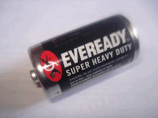
Battery

How do electric current flow from those terminals?

We are to use flash light as an example. If you are to turn the switch ON, a chemical reaction takes place inside the battery where electrons are produced. 

Electric current will be generated out from the battery and it will flow starting from the positive terminal. The current will then flow through the bulb and back to the negative terminal.

Lightning During the Bad Storm Weather Condition

Everybody has already experienced a bad storm where the condition of the weather causes several lightning flashing above the sky

Along with the lightning is the thunder which produces a terrible roaring sound where legends tell that the gods are angry. If you study mythology, Zeus is the name of the god that has the power to use lightning.

It is important for you to know that lightning is a very powerful energy which makes it highly dangerous. This is the reason why your parents warn you not to go out on bad weather condition. 

You have to know that there are already numerous incidences where humans got hit by lightning putting them in a terrible state of condition.


Lightning is actually a giant spark of electricity which is the same as the power generated from your wall outlet. 

You might have also noticed the so called “Static Energy”. This usually happens when you try to comb your hair or take off your nylon sweater especially in a dark room. 

You will notice tiny sparks of electricity and they are just exactly the same as the lightning but quite smaller and not dangerous.


In addition to the topic, do you know that light travels faster than the sound?

The perfect example is the lightning and thunder. These two natural occurrences both happen at the same time but the lightning comes first before the thunder because it travels faster down the ground.

Electricity is what makes the Whole World Work

You might have already encountered one of the most amazing creatures which are the Electric Eels. They are an aquatic animal that has the capability to generate powerful electricity out from their own body. 

It acts as their protection against any threat which is advice not to get in contact with them if you found any of these creatures washed on the beach.

However, Electric Eels are not the source of our electricity which we use in our houses. The electricity that we use on our daily life comes from huge power stations particularly a large dam of water. 

Power Stations are composed of generators which converts the force of the flowing water into energy. This is referred as the conversion of mechanical energy into an electrical energy

This can be done through the relative motion between a magnetic field and conductor.


Around the world, electricity is now an important necessity. You phone is powered by electricity which you use to contact the authorities on emergency cases. 

All companies needs electricity to run their computers and machines to process their products. Hospitals these days now use high-tech medical equipment which requires electricity to power them up. 

These are only just a few examples about how electricity is important in our daily life.


Due to the increasing number of our population, electric bills tend to increase where you may find paying it as expensive. 

Thus, you need to learn how to conserve energy by turning OFF any of your equipment that are not in use such as TV set, Radio, Lights and etc…

The Difference between Conductors and Insulators

On this world, it is filled with objects containing electrons which are tiny particles of electricity. They are categorized into two different materials which are the Conductors and Insulators

Conductors are materials that allow electric current to flow through while the Insulators are non-conductor that doesn’t let and electric current to flow.

You can perform a simple experiment to learn how to identify an object whether it is a conductor or an insulator. 

What you just need is a multi-meter tool and a collection of various objects found around your surroundings. 

Set your VOM or DMM at the resistance mode adjusting at the level which will flick the pointer of your VOM or set the output display of your DMM into infinity when you try to contact both of the two probes.

After you have setup your equipment, take the objects one at a time and use your multi-meter’s probe to check each one of them. 

Make sure that you are not holding the tip of the probe when doing this simple experiment. 

If the object you test makes the pointer of your VOM flick to the other side or your DMM shows the infinity symbol or several numbers then it is positive that the object is a conductor. 

Otherwise, the object is an insulator if no action can be observed from your VOM’s pointer or DMM output display.


If you do not have a VOM or DMM for this experiment then you will need a battery and a light bulb. You need to make sure that the bulb has a rating suitable for the battery to make it light. 

Connect them with wires but you have to make one of the portions of the wire open which will act as your probe. Just like the procedure above, take an object and use the open wires as your probe.


If the objects you have tested made the bulb lights up then those materials are conductors. Else, if the object does not make the bulb light then it is non-conductor or insulator.

Broadcasting – Transmission of Electromagnetic Radio Waves

It is by no doubt that you have already watched your favorite TV stations or tuned-in into your radio to listen into the sound of music. 

Okay, maybe not if you are still living under the cave for years staying on some remote places where technology couldn’t reach.

Technologies like your Radio, TV, Mobile Phones and other devices that transmit information through space can be termed as “Broadcasting”

To provide you more of it’s general meaning, it is the process of sending out information in all directions.

How it works:

Let’s take your TV as an example, all TV stations does have their powerful transmitter which radiates electromagnetic radio waves in all directions. 

If your location has been covered by the transmitted electromagnetic waves then your TV can receive the signal through its receiver antenna.

To tell you a brief history about the improvement of radio waves signal, it all began from the invention of Dr. Lee De Forest who discovered the vacuum tube. 

This device can actually amplify the short electrical signal converting it into its original form. 

However, it has been replaced by Transistors in 1948 by Bell Telephone Laboratories because it offers more advantages than the tube. 

You can read more information at this post entitled “Development of Wireless Communication.

Carrier Modulation Technique:

Signal


Carrier


Output


The carrier itself is the electromagnetic wave that holds the information. It is then to be processed through modulation technique to output the desired and understandable information for use to interpret. 

There are several Modulation Techniques but the most common among them are the Amplitude Modulation (AM) and Frequency Modulation (FM).

Development of Wireless Communication

The theory of wireless transmission started way back on 1887 by a German Physicist by the name of Heinrich Hertz

His work has been continued by other famous physicist until in the year 1895. Guglielmo Marconi, an Italian Inventor was able to develop a radio system that finally achieved long distance wireless transmission. 

The demonstration has been conducted across the Atlantic Ocean in 1901 and it’s a great success.

After Guglielmo’s success with his long-distance wireless communication radio system, it has been immediately followed with more improvement through the use of the vacuum tube. 

It was in the year 1906 when Dr. Lee De Forest introduces his Audion Tube which can relatively amplify weak electrical signals. To tell you more about Dr. Lee De Forest, he is known as one of the fathers of the Electronic Age.


Due to the invention of vacuum tubes, radio broadcasting has been at the verge of rapid progress. In 1920, KDKA station was the first to broadcast regular scheduled programs under the AM radio band

As for the FM, it caters for sound programs which started in the year 1939. It’s only in the year 1961 when Stereo broadcasting on FM radio has started.


Television broadcasting has been introduced in July 1941 but it only hits its popularity in the beginning of 1945. Colored-TV was adopted in 1953 up to this very current date.

Going back about the Vacuum Tube, another invention has been discovered in 1948 at Bell Telephone Laboratories. It’s all about transistors which exactly have the same function as the tube but it works by controlling the electron flow through germanium and silicon.


There actually more advantage of using a transistor over the vacuum tube. Some of these advantages are its smaller size and efficiency.

Discovery of Electricity and Magnetism

On the previous discussion, it has been discussed that Heinrich Hertz ended up his technological quest about electromagnetic waves where he was able to demonstrate wireless transmissions.

It was in the year 1820 when another dedicated Danish Physicist made an effort to continue Heinrich Hertz work. 

He was Hans Christian Orsted, his discovery was all about electrical currents wherein it can produce magnetic field. 

According to history, Orsted’s discovery of electromagnetism was just coincidental. He noticed on one of his lectures that a compass needle was deflected from the magnetic north when an electric current has been applied.


Eleven years later (1831), a British Physicist named Michael Faraday even made more interesting discovery where he has concluded that a magnet in-motion can induce electricity to be produced. 

He has made a lot of accomplishment and the most renowned physicist about magnetism.


It was in the year 1895 when another British Physicist named James Clerk Maxwell formulated more about the electromagnetic waves that has been demonstrated by Heinrich Hertz. 

His mathematical equation derives both electricity and magnetism which is particularly known as electromagnetic field.


Today, most people are now familiar about magnets. You can encounter them on toys even on simple objects. 

The applications for magnetism are actually broad that range from security to health care, communications, transportation and other aspects of our day-to-day life

All of these great improvements on our technology came from the effort and discoveries of these famous physicists. 

You should take into consideration about remembering them when using any of such devices into your own needs.

Heinrich Hertz – Founder of Wireless Technology

Any form of communication that does not require cable connections or any materials that connects between the transmitters and receiver is considered as a “Wireless Transmissions”. 

On this generation, we often communicate via this method and such devices are mobile phones, radio, televisions and etc…

All of these valuable gadgets that allow us to communicate even at far distances started from the work of a German Physicist. 

He was Heinrich Hertz and he was the first to demonstrate how electromagnetic radiation travels through space.


In the year 1887, a lot of test and experimentation has been done by Heinrich Hertz. Through his effort and hard work, his demonstration was a success that thoroughly made a huge technological advancement on our communication technology. 

Although, the distance of transmission that Heinrich Hertz demonstrated was just only a few feet away. Anyway, the most important part is that he was able to prove that it is possible for radio waves to travel from one place to another eliminating the need for cable wires.


Apart from his successful experiment with radio waves, he has proven that the radio waves also travel exactly with the same velocity with the light waves. 

Actually, these radio and light waves’ falls under the category of the “Electromagnetic Waves”. The term Electromagnetic was simply a combination of the two words which are electricity and magnetism.


More examples of electromagnetic waves are heat radiations, cosmic rays, x-rays and any equipment that has the capability to transmit signal through space without relying to cable wires.

Electronics and Radio Communications

Electricity is the main source of power for all our devices to make them work. Electronics and Radio Communications are just the two practical applications that we are going to focus on this site.

If we are referring about Electricity, your first impression might be about your wall-outlet where you often use to plug-in your equipment. 

Other than your wall-outlet at homes, batteries are also another source of electricity allowing you to use smaller type of devices such as mobile phones, flash-lights and etc…


On this generation, we are happily enjoying the benefit of being able to be entertained with our radio components. 

You can always turn it ON especially on the morning to lighten up your day by listening to your favorite stations. But, did you know the history about the radio?


Radio is actually the abbreviation of “Radiotelegraph” or “Radiotelephone”. To bring you to the past, Radiotelegraph was the ancestor of today’s radio. 

It is the first device to establish wireless connection in the form of dots and dashes which is known as the “Morse Code”.

How about Electronics?

You should grab your Chemistry book and read a few details about electrons because it’s where the word electronics has been derived. 

Electrons are tiny particles of electricity found almost on every material around us. It is impossible to see them with our barely naked eyes where it requires highly specialized equipment to check them in action.

Electronics always come together with electricity. It’s requires the electrons responsible for generating the action to make your devices work.


Finally, Radio and Electronics are both based on the fundamental laws of electricity. They are somewhat closely related regardless of their practical applications. 

To make it clear, a good example is your microwave. This home equipment allows you to heat or cook your food at accurate specified period of time. 

The electronic part is the practical application of the microwave to produce heat but at the same time it also generates radio waves.

Difference Between Alternating Current and Direct Current

You might not be aware that there are two different types of current that we use on our daily life activities. 

They are the Alternating and Direct Current. Alternating Current are commonly used in high-powered equipment. 

The current on those Electric Poles are also in terms of an Alternating Current. Direct Currents are commonly used in smaller devices such as your Mobile Phone, Laptop, iPod and etc...

Students studying under the field of Electronics or Hobbyist are already aware that currents can be converted from one form into another. 

This can be done through a simple circuit called "Converter" and "Inverter". The circuit composes of a Transformer responsible for the conversion of the currents.

DC or Direct Currents

DC is the simple type of current similar to the electrical power generated by the batteries, natural static occurrences and lighting. 

It can be stored in various methods and consumed by the circuit through operation. The flow of current goes in one direction starting from the positive towards the negative. 

The use of this type of current are applied on low powered devices.


AC or Alternating Currents

AC currents are a lot more complicated to explain unlike the DC where the current travels in a single direction. 

Alternating Current doesn't have a constant voltage where it runs through a sinusoidal wave pattern. 

It behaves by starting from the Zero level then increases to the maximum value and goes down to the minimum level before starting back again from the zero. 

Moreover, this is the type of electricity that you are using to power-up those appliances in your own homes.


Computing for the value of the AC signal requires you to determine the RMS (Root Mean Square) Average of the Voltage. In general, it is the same electrical value in terms of DC current. 

So if one of your appliances provides the voltage specification then it is in terms of the RMS although some are not but has to be clearly specified in another term of unit. 

In western countries, they commonly use AC Voltages that ranges around 100 to 115 AC Volts. Some East or Asian countries makes use of 200 to 220 AC Volts.

Most questions that may arise is that, "Why does the main source of electricity has to be in the form of an Alternating Current?".


The answer to this question is because AC Voltages are a lot easier to convert from one level into another. 

This can be done through the use of a Transformer, an electronic component made out of winded coils. 

This will allow any equipment to reduce energy loss which is completely beneficial for everybody to use.

The Theory Behind Metal Detectors

There are hundreds of Metal Detectors that are available on the market and they usually come in expensive prices. 

As an Electronic Hobbyist, it might come across your mind on building this type of project and perhaps sell them for a cheap price on those Treasure Seekers. 

If you are going to look through the theory behind building a Metal Detector then you will be surprised on the simplicity of its circuitry.

The primary object that makes the Metal Detector works and to locate buried objects is the antenna, plate or the scanner. 

This part composes of coils winded around in circular direction. There is a computation on the required number of turns and diameter for the loop depending on the type of circuit design that you wish to build.


This type of equipment works by generating a powerful magnetic field around the loop or antenna. The magnetic field will travel its way down through the ground until a metallic object will be hit. 

If it does then the magnetic field will travel or bounce back into the antenna where the circuit will process the signal either in a form of sound or light indicating that there is a buried item under the ground.

Metal Detectors that are personally built are called "Home-Made" but does it works or performs well enough like those commercial products?

According to the latest news that I've read, there is this one guy who cannot afford to buy his own electronic detector thus he decided to build himself since the cost is a lot cheaper. 

After he had successfully completed his own project, he tested it on his backyard and to his surprise, he found a chest containing hundred pieces of gold coins. 

The treasure was buried by a depth of around 12 to 24 inches.

So does home-made type of detector as good as the commercial products?

The answer is no because Commercial-Made Metal Detectors can detect deeper buried items and those that have sophisticated adjustments can even distinguish the target object's shape and type whether it's Gold, Metal, Aluminum and etc...


Moreover, according to some professional treasure hunters, no matter how powerful or weak are your tools for searching the success of being able to find valuable items can only be acquired through experience.